KICK START MSP430 WITH Energia + CCS + Eclipse + IAR Embedded Workbench in Windows.
- Dec 2, 2017
- 12 min read
Hello everyone,
Today I am gonna show you guys, how to set up MSP430 for the first time in all the four IDE's with delay function implementation using loops, timers and finally, to blink an inbuilt LED efficiently.
INDEX
Prerequisites Setting up Energia for MSP430
Embedded C coding in MSP430 : basics explained
Codes for LED blink (without timers)
Basics of timers
Code for LED blink (with timers)
Setting up Code Composer Ctudio
Setting up Eclipse for MSP430
Setting up IAR Embedded Workbench for MSP430
Alright, let's make our MSP blink.
Hardware and software requirements:
A Pentium-compatible PC with Microsoft Windows XP(SP3), Vista(SP2), Windows 7, or Windows 8. Both 32-bit and 64-bit variants of Windows are (officially) supported. Windows 10 worked fine for me.
Internet Explorer 7 or higher, connected to the internet.
At least 1 GByte of RAM, and 2 GBytes of free disk space.
PDF Reader to access the product documentation
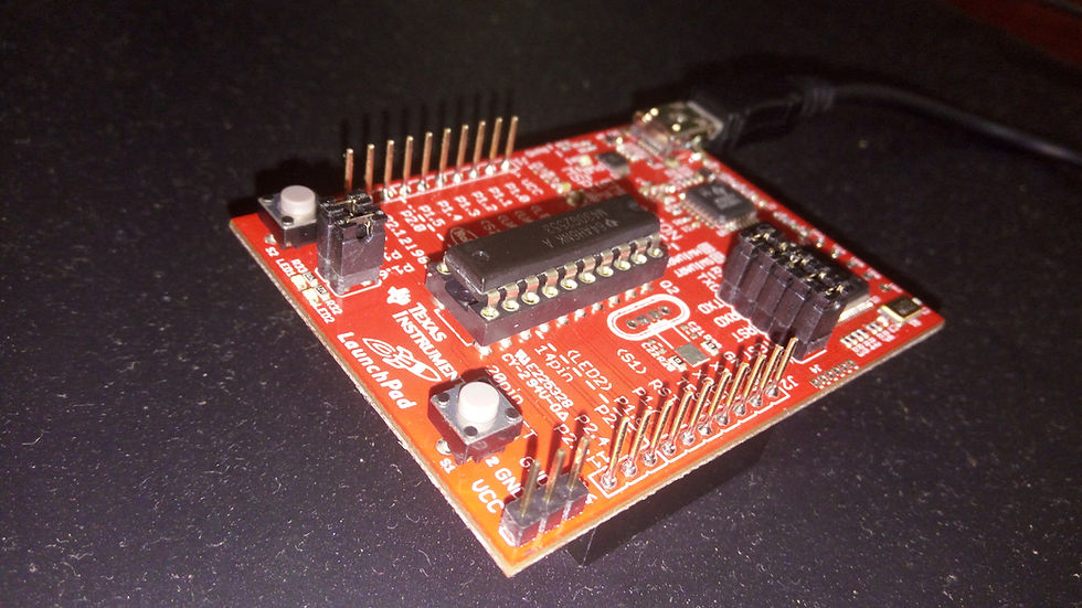
An MSP430 series development board (I used MSP430G2553 Launchpad kit)
Check if your Windows OS is 32-bit (x86) or 64-bit (x64) version:
Go to Start menu -> Control panel -> System and Security -> System.
Under system type, note down the windows bit version.
Install the Visual C++ redistributable packages/libraries to eliminate common “.dll” errors.
Visit: http://getintopc.com/softwares/utilities/visual-c-plus-plus-redistributable-packages-free-download/ to download the various versions of VC++ packages.
32-bit users install 32-bit packages alone while 64-bit users install both the 32-bit and 64-bit packages.
Install JRE ( Java Runtime Environment) or JDK (Java SE Development ) for CCS and Eclipse to work.
Search the web with the keywords “JDK download” or visit http://www.oracle.com/technetwork/java/javase/downloads/index.html
Click on “JRE download” (or “JDK download” if planning to develop Java applications. JRE file size is less compare to JDK file size). Make sure you download the bit version similar to your OS.
Accept License Agreement -> Download windows offline version.
Navigate to the downloaded folder -> Click open the application starting with “jre…” -> Install -> Close.
If the drivers did not install during/after the software(IDE) installations or fails to work properly, http://www.ti.com/tool/mspds is the link to download the MSP driver application.
SETTING UP ENERGIA FOR MSP430
Download Energia
Navigate to the downloaded folder and select the folder named “Energia – (version no.)- (OS name)”. Use 7 zip (or similar software) or inbuilt extract tool (in Windows 10, below the title bar of file explorer) to unzip/extract the downloaded file.
It’s a portable version. So the file contains the application, directly named as Energia. Double click to open.
Navigate to Tools menu-> Board ->
Select your board name.
Boards Manager -> Type -> Updatable (from the drop-down) -> more info -> select version (select latest version from the drop-down) -> Install. *The above method is important to eliminate errors.
The interface is very familiar for Arduino users. Go to File menu à Examples à Basics à Blink.
Connect your board to the computer using the USB cable.
Go to Start menu -> Device manager -> Ports -> find the COM number’ *Make sure the drivers are installed properly (no yellow signs).
Navigate to Tools menu -> Ports -> ’Select the COM number that you found in device manager’
Press CTRL+U to upload. Watch the red led blink!
The codes should be explained at http://energia.nu/Reference_Index.html.
Embedded C coding in MSP430: basics explained
Void main (void)
It’s a subroutine function that is automatically executed only once, in the beginning. To keep looping a program, say keeping the LED blinking continuously, we use loops as shown below
WDTCTL = WDTPW + WDTHOLD;
Used to prevent watchdog timer from resetting our MSP430 thinking that the CPU is stuck!! Visit https://os.mbed.com/cookbook/WatchDog-Timer for more info.
for(;;){code to be looped eternally} , while( 1 ){ code to be looped eternally} , etc…
The above codes are used to execute the code contained in them continuously, again and again without limit. Similar to void loop in Arduino.
for ( i=1000 ; i>0 ; i-- ) {} , __delay_cycles(##); , etc…
The above codes introduce a finite loop in the program thus delaying the execution of the next code.
for ( i=10 ; i>0 ; i-- ) {} is a finite loop where microcontroller will keep decreasing the I till i>0. So we have a delay of for loop here. Usually, we set i = 10000 or more to achieve a visible blink in LED
__delay_cycles(##); is an intrinsic function specific to MSP430 where one can tell the compiler to feed some functions to waste the specified number of clock cycles (replace ## by the number of cycles to waste).
0b00001000 (in binary) = 010 (in octal) = 8 (in decimal) = 0x08 (in hexadecimal). Here, the bolded numerals/alphabets are syntax to represent different numbers in different number system (note that decimal has no special syntax).
BIT0, BIT1, BIT2…. BITN can be used to represent 0b00000001, 0b00000010, 0b00000100,….
We use a lot of bitwise operators like ^=, |=, etc.... Visit https://en.wikipedia.org/wiki/Bitwise_operations_in_C
One can talk to Microcontrollers through Registers!!!
Insight To access a register, we have used the names of the registers defined in the header file (take a look at the header files in the workspace).For example, PnDIR, PnOUT are two of the many other registers used to control the GPIO pins in MSP430 (can be called as special function registers or SFRs). As they are GPIO pins, P in PnDIR represents port (abbreviation), DIR for direction and n for the port number. Each port controls 8 pins (usually). For example, our MSP430 has ports Pn = P1, P2 where (n=1,2).
To set the first pin in port 1 (labelled P1.0) as output, we write “P1DIR = 0b00000001;” The first pin is controlled by zeroth bit. Let me split and explain,
Similarly, we can write P1DIR = BIT0; this is same as P1DIR = 0b00000001; Writing in binaries to registers is a headache (not much human-friendly) so we use identifiers like BIT0, BIT1, …
Some special function registers have even more specific bit names (identifiers) to make things simple. Writing TA0CTL=ID_3; is same as writing TA0CTL=0x00C0; in timer0A control register, to divide its clock source by 8 (8hz will be fed as 1hz to timer A). Similarly, we have a lot of identifiers specific to a register like ID_2, ID_1, DIVS_3, …
Visit the link below for more pdf on C used in MSP430: http://downloads.ti.com/docs/esd/SLAU132K/
Remember: Header file is your accurate cheat code.
Codes for LED blink (without timers)
//Method 1: Blink using finite loop delay.
#include "io430.h"
//header file Error? Uncomment the header file below and delete the //above
//#include "msp430.h"
void main (void)
{
WDTCTL = WDTPW + WDTHOLD; P1DIR = BIT0;
volatile unsigned int i;
for(;;)
{
P1OUT ^= BIT0;
for(i=10000;i>0;i--)//try changing the values.
{}
}
}
//Method 2: Blink using intrinsic delay function.
#include "io430.h"
//header file Error? Uncomment the header file below and delete the //above //#include "msp430.h"
void main (void)
{
WDTCTL = WDTPW + WDTHOLD;
P1DIR = BIT0;
for(;;)
{
P1OUT ^= BIT0;
__delay_cycles(100000);//try changing the values
}
}
BASICS OF TIMERS
"Blink using Timer is efficient. Above two methods waste the CPU cycles by polling and are not energy efficient. Using interrupt is the best way to improve the overall efficiency of this program as it does not load the CPU often."
We use timers (Layer 3) that sources it’s clock from clock modules (Layer 2) which sources it’s clock signal from main source clock (Layer 1: Oscillators that actually produce frequencies within tolerance).
Clocks are microcontroller specific. MSP430G2553 has three main source clocks –
DCO (digitally controlled clock),
VLOCCLK (very low power low frequency internal clock ≈ 12KHZ),
LFXT1CLK (Low frequency external clock ≈ 32KHZ. High frequency mode is marked absent in datasheet for msp430g2xx3 series. May be available for others).
XT2CLK is another external clock provision for high frequencies, which is absent in MSP430G2553.
There are two timers available in MSP430G2553 - Timer0_A and Timer1_A. Timer B is absent.
Main clocks (Layer 1) cannot be sourced directly by timers(Layer 3) but through clock modules(Layer 2) i.e Layer 1 has to pass through Layer 2 to reach Layer 3. Alright here comes the big picture!

Control registers for all the above basic modules (except 11 and 12) are,
DCO is controlled through DCOCTL (DCO control register) and bit0 to bit3 of BCSCTL1 (basic clock system control register 1) and bit 0 of BCSCTL2 (basic clock system control register 2).
XT1 and XT2 are controlled through bit 6 and bit 7 of BCSCTL1 and through BCSCTL3 (basic clock system control register 3)
ACLK is controlled through bit5 and bit 4 of BCSCTL1
SMCLK is controlled through bit1 to bit3 of BCSCTL2
MCLK is controlled through bit4 to bit7 of BCSCTL2
Timer0A is controlled through TA0CTL (TimerA0 control register).
Reference: MSP430 clock system and timer by Yin Wang – northeastern university, and MSP430 Family Guide.
Code for LED blink (with timers)
//Method 3:Blink using timer
#include "msp430g2553.h"
//header file Error? Uncomment the header file below and delete the //above //#include "io430.h"
void main(void)
{
WDTCTL = WDTPW + WDTHOLD; // Stop WDT
DCOCTL = 0x00;
DCOCTL = CALDCO_1MHZ;
//uses calibration data from registers to tweak DCOCTL register
BCSCTL1 = CALBC1_1MHZ ;//uses callib. data to tweak BCSCTL1
BCSCTL2 = DIVS_3;
//actually sets divider as 8 for SMCLK (sourced //from DCO/8)
// Selects DCO as source. See the MSP 430 family guide for bit reference
TA0CTL = TASSEL_2 + ID_3 + MC_1;//control reg. for timer A0
TACCTL0 = CCIE;
//control reg. for compare/capture register 0 in timer A0
TA0CCR0 = 1249;
P1DIR = BIT6;
__bis_SR_register(GIE);
//directly affects the CPU status register to enable global interrupt
LPM0;
// to put our CPU in low power mode-0 to reduce power consumption.
}
#pragma vector = TIMER0_A0_VECTOR
// I only have hints about this line of code. Once the interrupt //vector defined here is active, the function below will be executed
__interrupt void Blinker(void)
{
P1OUT ^= BIT6;
// Toggle P1.6 for every clock input (with divider)
}
//Error:: IAR might crash while debugging --- //CCS works good //formula blink frequency = (callib. frequency (1MHZ))/(2 x divider x counter) //2 arises due to the fact that 1 interrupt for ON and one for OFF //to check the efficiency, try removing the Vcc jumper and measure //the current for all 3 codes.
SETTING UP CODE COMPOSER STUDIO
Search using the keywords “CCS download” in the browser or enter the URL http://processors.wiki.ti.com/index.php/Download_CCS. Download the latest version.
*CCS ver7 does not support Windows XP.
Navigate to the downloaded folder and double-click the file named “CCS_setup_ver#”.
Approve UAC, if any. It’s advisable to turn off your antivirus software momentarily when the software installs.
Click “Continue”
Check “I Accept…” if you accept the terms of the license
Click Next -> Choose the installation folder or leave it to default -> Next -> Check the “MSP430 ultra-low-power MCUs” box -> Next ->Make sure “MSP flash/fram emulation tool” is selected-> Finish
The installation process will continue. Wait until it completes. For web installers, the additional files will be downloaded from the internet during this process.
Once installation completes, go to Start menu -> Search for “CCS” -> Click open
Choose a workspace folder from the dialog box.
Go to Project menu -> New CCS project à”New CCS project” dialog box will open.Under ”New CCS project” dialog box,
Type your ‘project name’ in project name text box.
Targetà ‘Choose your MSP430’.
Project templates and examples -> Choose “Empty project (with main.c)” (or anything of your choice) -> Finish. The text editor should be available now to enter the code.
Enter the codes.
Press CTRL+B / Go to Project menu -> Build all.
Connect your MSP430 to PC through USB.
*Make sure the drivers are installed properly (no yellow signs).
Press F11 / Go to “Run” menu -> Debug -> Proceed.
Press F8/ Go to “Run” menu -> Resume
SETTING UP ECLIPSE FOR MSP430
Search with the keywords “eclipse download” in the browser or visit: https://www.eclipse.org/downloads/
Find and click on “download packages”
Select your OS from the drop-down menu on the webpage
Choose a way below:
Way 1: Web installer
Scroll down to find the “Eclipse Installer”. Click on the “32bit | 64bit” (the bit version of your OS) link to download the web installer.
Way 2: Package installer
Scroll down to find “Eclipse IDE for C/C++ Developers”. Click on the “ 32bit | 64bit” (the bit version of your OS) link to download the web installer.
Click on download
Navigate to the downloaded folder. Double-click the file named “eclipse-inst-win(bit version of OS)”
For "Way 1 "users, Select Eclipse IDE for C/C++ Developers
nstallation folder, Java version, product version and the bit version to install. Click install. The installer will download/verify the necessary file from their database to start the installation.Choose the i
After installation is complete, (click on keep installer to save them for future use) click on the settings button in the title bar -> Update. Wait till it updates.
Go to start menu -> search with keywords “Eclipse”-> Click open. “Eclipse launcher” dialog box will open.
In the “Eclipse launcher” dialog box -> Browse -> choose the directory for your workspace -> Launch. Wait for the application to load.
Go to Help menu -> Install new software -> Type http://eclipse.xpg.dk in the “Work with” text box -> Add -> Give any name -> Ok -> Under the “work with” text box, check the box named “msp430” -> Next -> Wait for the file to download and install -> Finish -> Restart.
You will find MSP430 menu in the toolbar of the eclipse.
Search the browser with the keywords “MSP 430 Toolchain for eclipse” or visit http://www.xpg.dk/projects/msp430/msp430-eclipse/ or https://openwsn.atlassian.net/wiki/spaces/OW/pages/11534370/msp430gcc+on+Eclipse+with+mspdebug+Preferred. Download the MSP430 toolchain for windows. Extract the downloaded file.
Go to “MSP430” menu -> Tools manager -> Add -> Browse for the extracted folder -> choose the folder that contains other folders named “bin”, “include”, “lib”… directly under it (or it will end up in error as the extract will create two similar folders, one inside another. Choose the innermost one) -> OK -> Select the Toolchain displayed under the Name column in Tool Manager -> Activate -> Close.
Go to File menu -> New -> C project ->
Give a project name.
Project type -> MSP430 Cross target application -> Empty Project
Toolchains -> MSP430 GCC Toolchain -> Finish
Go to File menu -> New-> Source file -> Type “any name.c” in the source file text box
Maximize the project explorer pane on the left (tricky to find).
ALT+ENTER or Right-click the “project name” in project explorer -> Properties -> MSP430 ->
Target MCU -> Choose your board/IC.
MSPDebug -> Driver -> tilib (try different option if it doesn’t work)
MSPDebug -> Protocol -> SBW (try different option if it doesn’t work)
Double click the “any name.c” file created. Enter the codes.
Press CTRL+S to save (This is important. Otherwise the code before saving will be compiled and uploaded).
Press CTRL+B to build all.
Connect the MSP430 to PC using USB.
*Make sure the drivers are installed properly (no yellow signs).
Go to “MSP430” menu -> Upload to target.
Look for the errors. Something similar to "can't find msp.dll "error might occur!
Search the web using keywords “MSP430.dll download” or visit http://www.ti.com/tool/MSPDS
Download MSPDS: MSP Debug Stack Developer’s Package and extract the downloaded file.
Search for the file named “MSP430.dll and MSP430_64.dll”. Select both of them and press CTRL+C.
Navigate to the folder containing MSP430 toolchain -> bin -> CTRL+V.
Now save the code and try uploading to the target again. The error should be gone.
SETTING UP IAR EW FOR MSP430
Make sure your pc is connected to the internet and open a browser. Enter the following URL: https://www.iar.com/iar-embedded-workbench/#!?architecture=MSP430& currentTab =overview.
It will get you to MSP430 information page. Scroll down to find the words MSP430 download free trial – expand the tree node by clicking on +.
Now click download software.
Navigate the downloads folder and click open the file named “EW430-####-Autorun.exe”
From the pop-up window select “Install IAR workbench”
In the “Installation wizard” select click Next -> Accept (if you accept the license terms) -> Next -> Select the folder to install/ or -> Next -> Custom/complete -> Next -> Install (for ver. 7.10)
Once installed, search for IAR keywords in the start menu. Click on the application shortcut.
The license manager will open for the first time like shown below (if not search for IAR license manager in start menu -> click open -> Menu “License” -> Evaluation license)
Click on the register. It will take you to a webpage in the browser where you have to fill in your credentials.
Make a choice between code size limited version- Kickstarter / the complete version for 30 days trial
The license number link will be sent to your E-mail ID. Click on the link in your e-mail to get the License number.
Go back to license manager, fill in the activation code and complete installation.
In IAR Embedded Workbench IDE window, click File menu -> New Workspace.
Now go to Project menu -> Create a new project. “Create new project” dialog box will open
Make sure to select the Tool Chain as MSP430 from the drop down and choose a template. For now, we will start with C template by expanding the C tree node and select main as shown above.
The save as dialog box will open where you can give your file a name and save it in your desired directory.
The panel on the left is called “Workspace”. Select the “debug” option from the drop down below.
Now right click on Your “Project name – debug” and select “options”.
Under category FET Debugger -> Connections -> Elprotonic USB-FPA
Under category General options -> Target -> Device -> Select your device.
Under category Debugger -> Setup -> Driver -> FET Debugger
(Optional) Under category C/C++ Compiler -> Optimizations -> Level -> None *If the above settings don’t work for you while debugging, try reconnecting the USB to the device / try fiddling with the options above / make sure if the device driver is installed properly in the device manager.
Connect the MSP430 to PC through USB. *Make sure the drivers are installed properly (no yellow signs).
Under workspace -> Project Name – Debug -> main.c <- double-click.
Enter the codes.
Project menu -> Rebuild all.
Now press CTRL+D / Click on “Download and Debug tool” in ribbon / Project menu -> Download and debug.
Happy embedding!
Disclaimer:
The information in this booklet is true, tested in Windows 10 and complete to the best of our knowledge. All recommendations are made without guarantee on the part of the author. The author disclaims any liability in connection with the use of this information.
This work is licensed under the Creative Commons Attribution-ShareAlike 4.0 International License. To view a copy of this license, visit http://creativecommons.org/ licenses/by-sa/4.0/ or send a letter to Creative Commons, PO Box 1866, Mountain View, CA 94042, USA.


Comments